What is Mother board?
In a mobile phone, the motherboard, also known as the logic board or mainboard, is the central hub that connects all the components like charging Jack, Sim jacket, SD Card port etc. and allows them to communicate, housing crucial elements like the CPU, GPU, RAM, and storage.
The mobile motherboard is like the brain of a smartphone, where various components are interconnected to ensure proper functionality. Below is a detailed guide to help technicians understand the key parts, their functions, and some basic troubleshooting tips.
1. Charging Jack (Charging Port)
- Function: This is the entry point for the charging cable. Its primary role is to charge the phone’s battery and enable data transfer between the phone and other devices like a PC or laptop.
- Importance: Without a functioning charging jack, the phone’s battery cannot be powered up or synced with external devices.
- Troubleshooting Tips:
- Check for physical damage or debris in the port.
- Use a multimeter to confirm if the port is transferring current.
- Ensure the soldering is intact while replacing the charging jack.
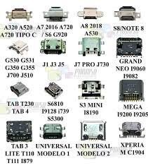
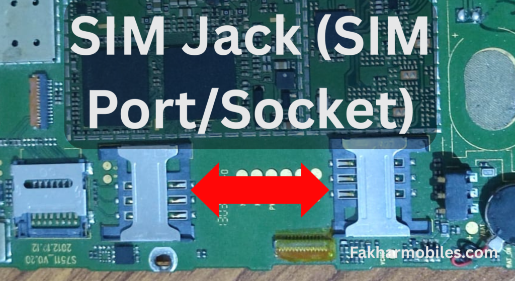
2. SIM Jack (SIM Port/Socket)
- Function: The SIM port holds the inserted SIM card, allowing the mobile phone to connect to cellular networks for making calls, sending SMS, and accessing mobile data.
- Importance: It’s essential for network connectivity and communication.
- Troubleshooting Tips:
- Inspect the SIM slot for bent or broken pins; replace it if damaged.
- Make sure the phone is reading the SIM card by testing on another device.
- Update the IMEI configuration if network issues persist.
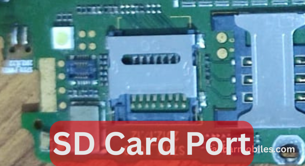
3. SD Card Port
- Function: This port is used to expand the phone’s memory by inserting an SD card, allowing storage of photos, music, documents, apps, and other files.
- Importance: Crucial for users who need extra storage space, especially on phones with lower internal memory.
- Troubleshooting Tips:
- Clean the port and the SD card with isopropyl alcohol if the card is not detected.
- Check for outdated SD card readers or firmware issues.
- Replace the SD slot if it doesn’t make proper contact with the card.
4. Speaker
- Function: The speaker outputs audio on the phone, whether for calls, notifications, or media playback.
- Importance: Essential for clear sound quality during calls and media consumption.
- Troubleshooting Tips:
- Check for blockages in the speaker grill.
- Use a multimeter to test the speaker’s continuity.
- Replace the speaker if it produces distorted or no sound.
5. Microphone (Mic)
- Function: The microphone collects audio input for calls, voice recordings, and virtual assistant commands.
- Importance: Key for communication and audio-based functions like video recording.
- Troubleshooting Tips:
- Ensure the mic hole is not blocked by lint or dust.
- Test it using diagnostic apps and replace if audio input quality is poor.
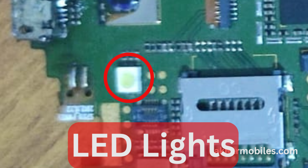
6. LED Lights
- Function: These are used for the phone’s backlight, camera flash, and sometimes as notification indicators.
- Importance:
- Backlight is crucial for display visibility.
- Camera flash improves low-light photography.
- Notification lights keep users informed.
- Troubleshooting Tips:
- Check for loose connections in LED circuits.
- Confirm brightness levels in the software settings.
- Replace damaged LED components.
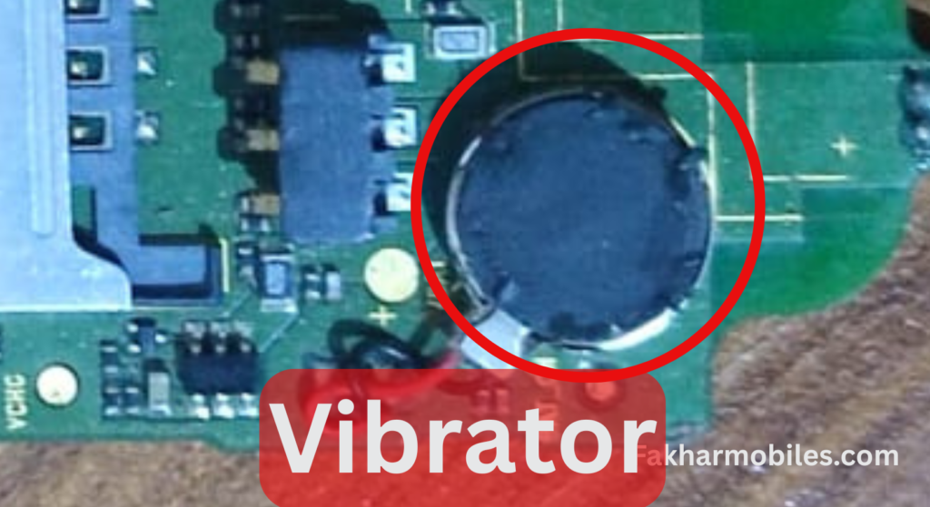
7. Vibrator
- Function: The vibrator motor generates vibrations for notifications and alerts.
- Importance: Useful for silent alerts, ensuring users are notified even without sound.
- Troubleshooting Tips:
- Test the motor using phone diagnostics.
- Check for loose contacts or broken connectors.
- Replace if the vibration is weak or not functioning.
8. Camera
- Function: It captures images and records videos. Modern phones may have multiple cameras for different purposes (e.g., wide-angle, macro, or portrait mode).
- Importance: A core feature for most users, especially for communication and social media.
- Troubleshooting Tips:
- Clean the lens to avoid blurry photos.
- Replace the camera module if it fails to initialize.
- Check for software updates when facing focus or resolution issues.
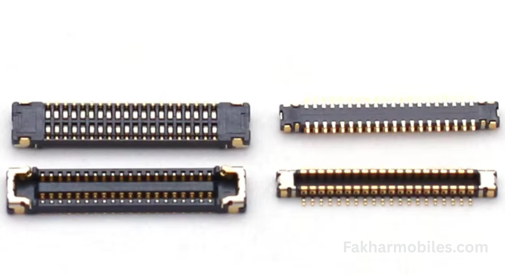
9. Connectors
- Function: Connectors act as bridges, supplying current and data to different parts of the phone, such as the battery, camera, fingerprint sensor, display, sub-board, LCD, and touch.
- Importance:
- Ensures smooth communication between components.
- Enables seamless functioning of all modules.
- Troubleshooting Tips:
- Confirm connector alignment and tightness.
- Inspect for corrosion or burnt marks on the pins.
- Replace faulty connectors with compatible replacements.
Additional Notes for Technicians
- Handle all components with care to avoid static damage. Use anti-static tools when working on a motherboard.
- Always test the functionality of parts after repair or replacement.
- Keep the firmware updated to prevent compatibility issues between hardware and software.
- Use a magnifying lens to identify micro-damages on connectors and slots.
By understanding these key parts and their functions, mobile technicians can diagnose and repair mobile phones more efficiently. Ensure you follow best practices for repairs and use quality components to maintain the phone’s performance and longevity.
SMD (Surface Mount Device) Components on a Motherboard
“SMD” stands for Surface Mount Device, referring to an electronic component designed to be mounted directly onto the surface of a printed circuit board (PCB).
1. Resistors
SMD components are fundamental to the functioning of a mobile motherboard, managing current flow and maintaining overall device stability. This guide provides detailed insights into various SMD components, their functions, troubleshooting techniques, and importance in mobile electronics.
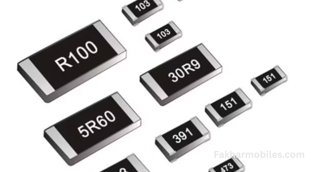
Appearance
- Color: Usually black with silver sides for soldering.
- Size: Available in both big and small dimensions depending on their purpose.
- Points: Two connection points, used to connect with the PCB.
Function
- Resist the flow of current in the circuit, effectively reducing and managing the current as per the device’s requirements.
- Their role is critical for controlling voltage levels and protecting components from overcurrent.
Measurement Unit
- Unit: Measured in Ohms (Ω).
- Symbol in Circuits: Represented by the letter R.
Importance
- Ensures components do not receive excess current, which could cause damage or malfunction.
Troubleshooting Tips
- Check for overheating or discoloration on the resistor, indicating stress or high current flow.
- Use a multimeter in resistance mode to measure and confirm the resistor’s value matches its label.
- Replace resistors if the value deviates substantially from the expected range or if it shows no continuity.
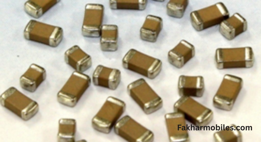
2. Capacitors (Polar & Non-Polar)
Polar Capacitors
Appearance
- Color: Generally black or brown with a white line or marking on one side, indicating polarity.
- Shape: Cylindrical or rectangular.
Function
- Stores and releases electrical energy in the circuit.
- Maintains a stable voltage supply by smoothing out fluctuations.
- Found in circuits requiring specific polarity, e.g., power supplies and audio amplifiers.
Importance
- Essential for filtering and stabilizing the power supply.
- Used in energy-demanding parts of the motherboard, such as processors and power management ICs.
Troubleshooting Tips
- Ensure the correct orientation during installation due to polarity requirements.
- Visually inspect for bulging, leaking, or corrosion, as these are signs of damage.
- Test capacitance with a capacitance meter and replace faulty capacitors with identical ratings.
Non-Polar Capacitors
Appearance
- Color: Typically yellow, Golden brown, or brown.
- Shape: Smaller than polar capacitors and mostly rectangular or disc-shaped.
Function
- Also stores and releases energy but does not require polarity for operation.
- Often used in circuits for blocking DC current while allowing AC signals to pass, known as coupling or decoupling.
Importance
- Commonly found in communication circuits, RF modules, and filters.
- Helps to improve signal quality by eliminating noise.
Troubleshooting Tips
- Inspect for cracks, burn marks, or physical damage.
- Measure capacitance and continuity to ensure proper operation.
- Replace damaged capacitors with identical or compatible ratings.
3. Inductors (Coils) and Their Types in Mobile Devices
Appearance
- Color: Typically black or green with a coil-like appearance.
- Shape: Rounded or rectangular.
- Size: Small, but varies based on current requirements.
Function
- Stores energy in a magnetic field and filters high-frequency noise in circuits.
- Works alongside capacitors for effective power management.
Measurement Unit
- Unit: Measured in Henries (H).
- Symbol in Circuits: Represented by the letter L.
Importance
- Protects circuits from sudden current surges and stabilizes voltage in the power supply.
Troubleshooting Tips
- Check for continuity using a multimeter; a break indicates damage.
- Inspect for corrosion or physical damage on its coil.
- Replace an inductor if it becomes loose or deformed.
Air Core Coils
Appearance
- Color: Often copper-colored with visible wire windings.
- Shape: Circular or rectangular with no core (empty inside).
Function
- Primarily used for filtering RF (radio frequency) signals.
- Found in antennas and wireless communication modules.
Importance
- Ensures proper signal transmission and eliminates interference in radio frequencies.
Troubleshooting Tips
- Inspect for broken windings or disconnected leads.
- Test for continuity to ensure current passes through the coil.
- Replace damaged coils to restore proper signal filtering.
Ferrite Core Coils
Appearance
- Color: Black or dark grey due to the ferrite material.
- Shape: Circular or rectangular with a visible core inside the wire windings.
Function
- Acts as a filter for high-frequency noise in power supply circuits.
- Found in areas where smooth DC voltage is critical, such as processors, display modules, and touch panels.
Importance
- Enhances the efficiency of power supply circuits by reducing losses.
- Protects sensitive components from noise-induced malfunctions.
Troubleshooting Tips
- Check for physical cracks or deformation in the ferrite material.
- Measure inductance using an inductance meter for proper operation.
- Replace the coil if its inductance value is out of range.
Iron Core Coils
Appearance
- Color: Black with a dense solid core.
- Shape: Compact and circular, typically heavier than ferrite core coils.
Function
- Filters low-frequency noise and stabilizes large current flows.
- Typically found in charging and battery circuits.
Importance
- Handles high-power applications efficiently.
- Ensures component longevity by maintaining consistent power supply.
Troubleshooting Tips
- Test continuity and resistance across the coil terminals.
- Replace if the coil is heating excessively, indicating damage to the core or winding.
Boost Coils and Buck Coils in Mobile Devices
Boost and buck coils are integral components in mobile devices, especially in power management circuits. They belong to the broader family of inductors and help in converting voltage levels as per the circuit’s requirements. Here’s a detailed explanation of their appearance, function, importance, and troubleshooting.
1. Boost Coils
Appearance
- Color: Typically black or dark grey with visible copper windings around a core.
- Shape: Circular or oval-shaped with compact windings around a central ferrite or iron core.
- Size: Moderate in size, depending on the required voltage boost in the circuit.
Function
- Boost coils are used in DC-to-DC step-up converters, which are circuits designed to increase the input voltage to a higher level.
- They store energy in the form of a magnetic field when current passes through them. When that current is interrupted, they release the stored energy, effectively increasing the voltage.
- Commonly found in circuits like LED backlights, displays, and charging systems that require higher voltage than what the battery provides.
Importance
- Enables devices to operate efficiently by supplying the necessary higher voltage for specific components.
- Essential for powering high-voltage components like flash circuits, displays, or camera modules.
- Supports smooth power delivery, protecting sensitive components from insufficient voltage.
Troubleshooting Tips
- Visual Inspection
- Look for physical damage, burning, or broken windings. A damaged boost coil might prevent the mobile device from powering specific components.
- Continuity Check
- Use a multimeter in continuity mode to ensure the coil’s winding is intact. If there is no continuity, the coil may need to be replaced.
- Voltage Output Test
- Test the voltage at the output of the boost converter using a multimeter. If the output is below expected values, inspect the circuit, including the boost coil.
- Heat Test
- Check if the boost coil is overheating during operation. Overheating indicates excess current flow or inefficiency in the circuit design.
2. Buck Coils
Appearance
- Color: Often black or grey with a ferrite or iron core surrounded by copper windings.
- Shape: Similar to boost coils, usually circular or rectangular.
- Size: Small to moderate, depending on the circuit’s current and voltage requirements.
Function
- Buck coils are used in DC-to-DC step-down converters, which are circuits designed to reduce the input voltage to a lower, usable level.
- They store energy and release it efficiently, ensuring the desired lower voltage is supplied to sensitive components.
- Found in circuits powering processors, memory chips, and other low-voltage components in mobile devices.
Importance
- Protects low-voltage components from overvoltage, ensuring the mobile device operates within safe limits.
- Maintains energy efficiency by reducing power consumption, which directly impacts battery life.
- Plays a crucial role in the stability and reliability of the device’s power supply.
Troubleshooting Tips
Inspect for audible buzzing or fluctuating voltage at the output. Noise indicates instability in the coil or surrounding circuit.
Visual Inspection
Look for burnt or damaged coils, as these can lead to improper voltage regulation or complete failure of the step-down circuit.
Resistance Check
Measure the resistance across the coil with a multimeter. An infinite or zero resistance reading indicates a problem with the coil.
Voltage Monitoring
Test the output voltage from the buck converter circuit. If it exceeds the expected level, the buck coil or associated components may be faulty.
Noise and Static Testing
4. Fuse
Appearance
- Color: Often white or colorful with markings indicating the current rating.
- Shape: Rectangular or cylindrical in surface-mounted formats.
Function
- Acts as a protective component, breaking the circuit when the flow of current exceeds safe limits. This prevents damage to other sensitive components.
Importance
- Extremely important for safeguarding the motherboard from short circuits or power surges.
Troubleshooting Tips
- Use a multimeter in continuity mode to check if the fuse is blown (no continuity).
- Replace with a fuse of the same rating to ensure proper protection without risking further damage.
5. MOSFET (Metal-Oxide-Semiconductor Field-Effect Transistor)
Appearance
- Color: Black with metallic pins, typically larger than standard transistors.
- Shape: Rectangular, designed to dissipate heat efficiently.
Function
- Works as a switch or amplifier, often used in power management circuits.
- Capable of controlling high current and voltage with high efficiency.
Troubleshooting Tips
- Test MOSFETs using a multimeter; check for short circuits between source and drain.
6. Zener Diode
Appearance
- Color: Black with a white or silver band on one side (indicating cathode).
- Shape: Small and cylindrical, similar to regular diodes but designed for specific use.
Function
- Allows current to flow in reverse direction when a specific voltage (called Zener voltage) is reached.
- Used for voltage regulation and as a protection device in circuits, preventing overvoltage.
Importance
- Ensures that the motherboard receives stable voltage, avoiding damage due to voltage fluctuations.
- Protects delicate components in power-sensitive areas.
Diodes
Appearance
- Color: Generally black with a silver or white band to indicate polarity (cathode end).
- Size: Tiny, often rectangular.
Function
- Allows current to flow in one direction while blocking it in the opposite direction.
- Protects other components from reverse voltage.
Measurement Unit
- Unit: Not measured directly, but its behavior is checked with a multimeter.
- Symbol in Circuits: Represented by a triangle with a line, indicating the cathode.
Importance
- Vital in circuits requiring unidirectional current flow, like in rectifiers and signal isolations.
Troubleshooting Tips
- Test with a multimeter in diode mode to check for voltage drop; an open or shorted diode requires replacement.
- Ensure the diode is correctly installed respecting its polarity.
Integrated Circuits (ICs)
Appearance
- Color: Black with multiple legs (pins) soldered onto the PCB.
- Shape: Square or rectangular.
Function
- Perform complex tasks like processing, controlling, and managing various functions in the device.
- Commonly acts as a brain for specific operations (e.g., power management IC, CPU, and GPU).
Importance
- Essential for advanced system operations, from basic tasks to high-end computing in smartphones.
Troubleshooting Tips
- Verify connections under a magnifying glass for weak or broken solder joints.
- Test supply voltage to the IC using a multimeter.
- Replace only if a complete IC module malfunction is diagnosed, as repairs are not typically feasible.
Final Tips for Technicians
- ESD Precautions:
Always use anti-static precautions when working with SMD components to avoid damage due to electrostatic discharge. - Magnification Tools:
Use a magnifying glass or microscope to identify cracks, burn marks, or loose connections on SMD components. - Multimeter Usage:
A multimeter is your best friend in testing the health of resistors, capacitors, and other components. - Soldering Skills:
Ensure sharp soldering skills to avoid damaging the PCB or neighboring components when working on SMD parts.
By understanding the role and troubleshooting techniques of key SMD components, technicians can ensure accurate diagnosis and reliable repairs for smartphones and other devices with PCBs.